Alejandro Senties Gutierrez, Applied Science
Abstract
Unmanned Aerial Vehicles (UAVs) have recently become a prevalent force in our society, one that can only be made more accessible in part due to 3D-printing. By testing a proposed UAV model, a greater sense of the feasibility and usefulness of these 3D-printed machines was attained. The study demonstrated that thermoplastic filaments are at a point where they can produce many functional parts. Therefore, the rapid prototyping times will allow for innovation with novel aircraft at an unprecedented rate. This can open the door to promising prospects in the aerospace industry, enabling many more people to begin to reap the benefits of these technologies.
Introduction
Unmanned aerial vehicles (UAVs) have been a rising force in the world, empowering dozens of industries to innovate in the manners in which they navigate complex operations. UAVs are replacing humans in areas that are high risk, remote, or in performing operations that benefit from a degree of automation and multi-vehicle coordination. From inspecting an oil refinery, performing a reconnaissance mission over hostile territory, to mapping terrain or serving as internet extenders, UAVs are becoming extremely versatile and powerful (Mohsan et al., 2022). With rising demand for UAVs, different processes for their manufacturing should be considered. 3D-printing has become a promising, widely-accessible additive manufacturing technique. 3D printers can produce quality, functional parts for prototypes or even final products, making them suitable for use in the production of UAVs. The quick iteration time between part versions can additionally allow for rapid upgrading and customizing of said parts, so UAVs can be better equipped to perform different tasks effectively. The purpose of this paper is to demonstrate the process of design, construction, and finally, the scrutinization of a proposed 3D-printed UAV, to determine the swiftness of iterating and evolving such UAVs over traditionally manufactured counterparts. The proposed UAV was inspired in part by the design of high-altitude long-endurance (HALE) aircraft, such as the General Atomics MQ-9 Reaper, which possesses a flight time of 27 hours (MQ-9A Reaper (Predator B) | General Atomics Aeronautical Systems Inc., n.d.).
Materials & Methods
Design Criteria
The tested UAV model was developed by firstly defining the intended mission capabilities of said UAV. The mission capabilities were defined as being an aircraft capable of low speed flight, no greater than 30 m/s. The flight ceiling desired was the legal limit for consumer or commercial UAVs in Canada, or 121 m above ground level or a building (Transport Canada, 2020). The maximum net weight could be the maximum thrust produced by the thruster adjusted for a power to weight ratio of 0.8:1 (National Aeronautics and Space Administration, 2021). As the thruster generated 1800 g of thrust, the maximum weight could be 2250 g.
The proposed UAV was designed based on three key considerations. Aerodynamic efficiency, inherent stability and producibility. The desired aerodynamic efficiency of the aircraft was high, which implied generating the greatest amount of lift with the least amount of drag, induced or otherwise. Inherent stability was the desired characteristic of the aircraft that results in the aircraft returning to level flight upon encountering a disturbance. Lastly, the producibility of the aircraft design was paramount as the aircraft manufacturing process was limited to the capacities of the 3D-printer employed. Limitations due to the material selection were also considered, since the primary material was a toughened variant of polylactic acid (PLA) filament (Filaments.ca, Colorfabb), as well as standard PLA filament (Polymaker).
Design Process
Efficiency. With the previous aerodynamic considerations, an airframe was designed. Aerodynamic efficiency was the first constraint, which would become reflected in the wing design. There were three variables of interest in the wings, which were the airfoil shape, aspect ratio and wing shape.
The airfoil shape of a wing affects the lift generation of the wing relative to its speed and orientation against the airflow. The angle against the wind is also commonly known as the angle of attack. By understanding the relationship between the airfoil thickness and the generation of lift, a thicker airfoil was selected as these were the best at generating lift at subsonic speeds (Munk & Glauert, 2022). However, the selection was further narrowed due to the producibility of the airfoil which for best results would need to have the most flat surfaces possible. The compromise reached was the Clark Y airfoil, which can be viewed in figure 1 (Polars for CLARK Y AIRFOIL (Clarky-Il), n.d.). The lifting characteristics of the airfoil can be appreciated in figure 2, which relates angle of attack (alpha) with its lift coefficient (Cl).


Figure 1. (Polars for CLARK Y AIRFOIL (Clarky-Il), n.d.) & Figure 2. (Polars for CLARK Y AIRFOIL (Clarky-Il), n.d.)
Secondly, the aspect ratio and sweep of the wing had to be optimized. The amount of induced drag generated by a wing of a given area can be reduced at the cost of maneuverability if the aspect ratio is increased (National Aeronautics and Space Administration, n.d.). Thus, a long and thin wing was selected, for the least amount of induced drag possible. Thirdly, the wing shape affected the lift distribution and thus efficiency of the wing, as referenced in figure THREE. While unfeasible to produce due to the curved shape, an elliptical wing offers the absolute best distribution characteristics (Ackroyd, 2013, 124). A tapered wing was selected, therefore reaching a compromise between the lift distribution for greatest efficiency and producibility.

Figure 3. (Dauntless Aviation, n.d.)
In addition to the wing design, the stabilizing surfaces at the rear of the aircraft could be optimized. A conventional tail design would consist of two horizontal surfaces and one vertical element, responsible for the pitch and yaw control of the aircraft, respectively. However, a configuration producing less drag can fulfill the same purpose, in this case a v-tail. Such an arrangement comprises only two elements, placed diagonally in the rear. The resulting net forces these are capable of producing fully satisfy the pitch and yaw control requirements for the tail of an aircraft, observed in figure 4 (SKYbrary, n.d.).

Figure 4. Pitch and Yaw requirements in the tail of an aircraft.
Finally, the placement of the electric ducted fan (EDF) was also chosen due to the benefits to the airflow past the wings. By placing the thruster at the rear of the aircraft, the airflow over the wings could remain cleaner for longer, improving efficiency (Stoop & de Kroes, 2012).
Static Stability. The next factor to be considered was inherent stability. The lateral stability of an aircraft depends on the self-leveling characteristics it displays, which can be controlled by the angle of the wings. An upward wing angle, formally known as a dihedral wing angle, allows the aircraft to self-right after encountering a disturbance. When a gust of wind rolls the aircraft, the lower wing is forced to fly at a higher angle of attack than the raised one. As seen in figure 5, this produces greater lift, returning the aircraft to a level position (“Static Equilibrium and Trim,” 2013, 33-71). The longitudinal stability of an aircraft can be improved by placing the center of gravity (C.G.) in front of the center of pressure (C.P.), as referred to in figure 6 (Federal Aviation Administration, 2016, 252; Talay, 1975, 154).


Figures 5 & 6.
Producibility. The producibility of said aircraft had to be seriously considered. As the production equipment was limited to solely a 3D-printer displayed in figure 7 (Anycubic Mega Zero 2.0), the size and shape of the parts printed could not be too large or intricate. The print area of the printer in question was 220 x 220 x 250 mm, which implied that all components greater than those dimensions had to be segmented, and assembly elements included in their designs. As gravity was a limitation of the print process, features with overhangs greater than 50º could not be printed. As such, as many surfaces of the aircraft as was feasible had to be flat. This affected the wings, primarily the airfoil shape. The v-tail elements, also known as ruddervators due to the nature of their operation, were selected as they would remove the need for a third rear surface, saving material and weight.

Figure 7. 3D Printer used (Gadget.ru, 2020)
Production Process
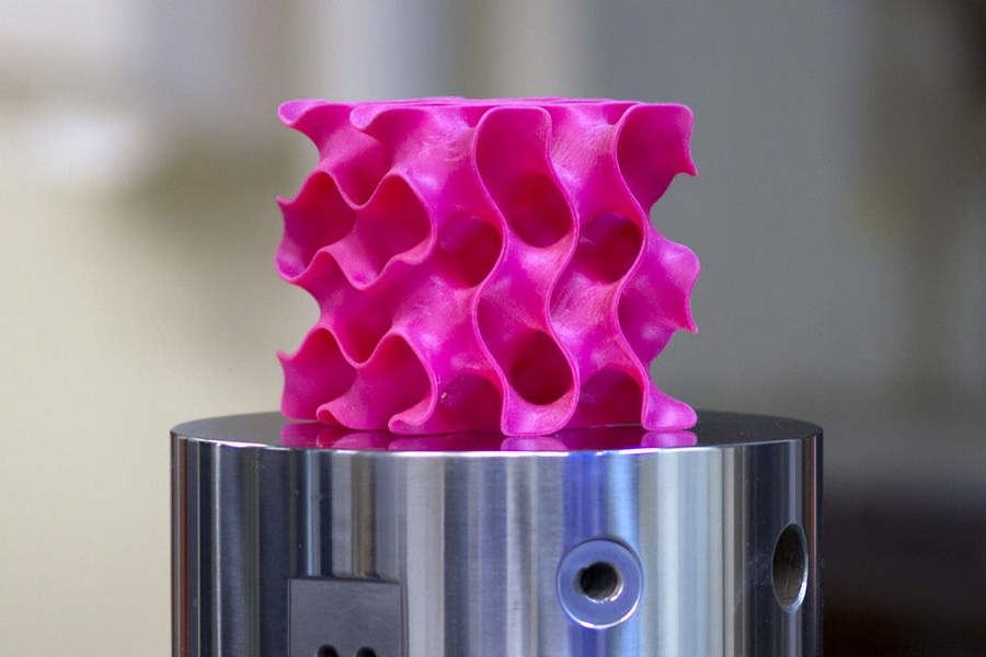
After the computer-aided-design (CAD) models were created and exported for printing, the slicing process began. The slicing of the models was the conversion from the tessellated geometry file into a file that the 3D-printer could interpret to reproduce the part. A few key parameters were modified from the default, namely the infill percentages and the infill type. The infill percentage expressed the solidity of the part, 0% being hollow and 100% being solid. The infill type was the infill design that could be selected, which in this case was set to gyroid due to the 3-directional strength element it provided, seen in figure 8.
The parts printed were the main wings, split into five pieces and three connectors each, the fuselage, split into five pieces, the nacelle, split into three pieces, the ruddervators, split into two pieces each, the front landing gear, split into six pieces, the rear landing gear, split into four pieces each, and the camera gimbal, split into seven pieces. A total of 49 pieces were printed, weighing a total of 1139 g and rendered in figure 9.


Figure 8 (Massachusetts Institute of Technology, 2017) & Figure 9.
Avionics installed consisted of a Raspberry Pi 4B 2GB RAM single-board-computer (SBC), an Emlid Navio2 flight controller shield for said Raspberry Pi, nine SG90 micro servos, an 80 A electronic speed controller (ESC), a QF-2827 2600 kV 70 mm EDF, an mRo SiK telemetry antenna, a GNSS antenna, a Raspberry Pi NoIR Camera Module V2, and a SIGP 6000 mAh 4S 70C Lithium-Polymer (LiPo) battery, all labelled in figure 10. The aircraft’s net weight increased to 2088 g, which was within the allowable limit. The two components that were particularly sensitive to EM interference were isolated using aluminum foil, which were the camera ribbon cable and the global navigation satellite system (GNSS) antenna. The components were further outlined in Table 1.
Table 1. Components.


Figure 10. Labelled Components
The airframe components were bonded together where applicable utilizing instant glue, distributing the adhesive over the broadest surface area possible. Critical joint surfaces were further reinforced using white duct tape. The final aircraft had a wingspan of 1.50 × 103 mm, a fuselage length of 760 mm, and a height of 298 mm, seen in figure 11.

Figure 11.
Testing Procedures
Construction. The first facet of the UAV that needed to be tested was the build quality. Before a test flight could be considered, the UAV had to be strong enough to endure aerodynamic testing without the potential to lose its physical integrity mid-flight. The first testing phase was concerned with the build quality of the wings, ruddervators and fuselage. Secondary components not critical to flight were ignored. The first test placed the wings under a simulated ultimate wing loading, calculated as the maximum expected G wing loading multiplied by a factor of 1.5 corresponding to the standard factor of safety (Federal Aviation Administration, 2023). G-force is a measure of acceleration based on earth’s average gravitational constant, 9.81 m/s2. The maximum wing loading can be determined by multiplying the maximum allowable weight by the maximum expected G-force. The UAV was classified as a normal aircraft as defined by the FAA (Federal Aviation Administration, 2022). This implied that the maximum G-force expected would be 3.8 Gs (Federal Aviation Administration & Department of Transportation, 2016, 219; Machado, 2020). The resultant value was 12825 g (2250 g · 3.8 Gs · 1.5), or 6412.5 g per wing. The loading needed to be evenly distributed on the wing, and the testing would be done on both sides of the wing. By distributing six assorted juice containers evenly on the wing, a weight of ≈6434 g was achieved. The weight remained for ten seconds on the wing, before it was rotated to the underside and the test repeated.
The second structural test was concerned with the torsion strength of the EDF nacelle joint with the fuselage. Due to the high force exerted parallel to the centerline of the fuselage, the bond had to be strong enough to sustain the full torque force on it for extended periods of time. To emulate the force of the EDF, a weight of equal magnitude to that of the thrust rating was placed on the center of the nacelle for durations of one, two, three, five, and ten minutes, as seen in figure 12. The constraint for allowable distortion in any given direction was 5 mm.
The final structural test strained the ruddervators, with a similar method as the main wings loading test. The ultimate loading was determined by utilizing the weight value for the wings, and reducing it accordingly for the area of the ruddervators. The area of the main wing was 82248 mm2, which corresponded with an ultimate loading of 6412.5 g. The area of the ruddervator was 18375 mm2, smaller by a factor of ≈4.4761. Thus, dividing the main wing’s ultimate loading by the factor yielded the new loading weight of 1432.6 g per ruddervator. A ≈1444 g weight was placed on the ruddervator, as seen in figure 13. The weight remained for ten seconds on the ruddervator, before it was rotated to the underside and the test repeated.


Figure 12 & Figure 13
Results
Structural Evaluation
The ultimate wing loading test was not passed by the wings, although displaying considerable flexion before fracturing, observed in figure 14. The second test directed at the ruddervators yielded the opposite results, with no perceptible damage found to the ruddervators. The tested nacelle joint was structurally sound, showing negligible distortion throughout the trial.

Figure 14.
Aerodynamic Performance
Due to a defective electronic speed controller (ESC), the delayed shipping of a compatible radio receiver, and the structural failures encountered, the completion of the devised flight tests was not possible.
Discussion
Aerodynamics
Aerodynamic tests that could have been performed had there been no component failures are the following: Lift generation would be the first element, which would involve accelerating the UAV to its cruise speed and observing if it remained in level flight. The test would operate the EDF at a sufficiently high velocity to allow the aircraft to take off, then be adjusted to maintain the minimum cruising speed. The minimum speed required for level flight would be calculated utilizing the lift equation rearranged for speed,

where L is the lifting force, the air density, Cl the coefficient of lift (which accounts for the angle of attack and airfoil shape), A the total wing area (both wings), and V the speed of the air. The angle of attack would be 0º, which corresponds to a Cl value of ≈0.40 for the Clark Y airfoil (“Polars for CLARK Y AIRFOIL (clarky-il)”). Lift produced by the ruddervators would be negligible, thus is omitted from the calculations. This yields the following speed,

which multiplied by a conversion factor of 3.6 provides a speed of 83 km/h.
A second trial, subject to the success of the first, would place the aircraft in level flight and then test the control authority of the control surfaces with respect to pitch, yaw, and roll moments. All angle measurements would be gathered from the on-board telemetry systems being fed by the primary inertial measurement unit (IMU) on the Navio2 flight controller. Firstly, pitch would be examined by deflecting both ruddervator surfaces to their maximum upward positions (30º). The time taken for the surfaces to rotate the plane to the critical angle of attack would be noted, if they were capable of it. Secondly, roll would be analyzed in a similar manner. Ailerons would be deflected to their maximum positions (30º) in opposite directions, and the rotation rate of the aircraft measured. Lastly, yaw would be assessed by deflecting the ruddervators to their maximum positions in opposite directions. The criteria for success would be a pitch rate of 5º/s, a roll rate of 20º/s, and a yaw rate of 6º/s in accordance with a rate two turn (SKYbrary, n.d.).
Airframe
The results demonstrated the strengths and weaknesses of the materials employed in the aircraft production, and of the methods used to manipulate them. Construction of a strong 3D-printed airframe still appears viable, given the plastic is reinforced in key areas. Namely, an enhancement could have been the inclusion of a carbon-fiber spar in the wings, bonded with an epoxy resin. A reason for failure may have been the printing direction of the wings. As the wings were printed vertically for greater airfoil shape accuracy and to allow for internal ribs, the layer lines were placed chordwise. Since the applied pressure created a bending moment about the chordwise axis, the layer lines were not oriented to deform lengthwise, but to detach from neighbouring layers as previously observed in the leftmost image in figure 14.
Potential areas of
further exploration include comparisons between 3D-printing materials, flight
characteristics of different airframes, and long-term durability/fatigue of
3D-printed components. The paper presented faced unforeseen hindrances in the
testing phase, which proves a limitation in the breadth of the results available
regarding aerodynamics. Notwithstanding, it can be inferred that producing
and/or upgrading a small UAV more swiftly than via conventional means of
manufacturing is plausible. Benefits would become further amplified based on
the size and quality of the 3D-printer employed, as larger printers would
remove superfluous complexity by reducing the part count. While the UAVs may
experience the same delays in supply-chains due to non-structural components,
the manufacturing of the airframe in its entirety is more straightforward with
a 3D printer. This only remains true given the intent is to rapidly iterate
through prototypes. In any case, it is imperative to note this novel additive
process would be highly unlikely to scale economically to large manned aircraft.
References
Ackroyd, J. A. D. “The Spitfire Wing Planform: A Suggestion.” Journal of Aeronautical History, 2013, p. 124. Aerosociety, https://www.aerosociety.com/media/4843/the-spitfire-wing-planform-a-suggestion.pdf. Accessed 14 March 2023.
Dauntless Aviation. “Wing Planform.” Dauntless Soft, https://www.dauntless-soft.com/PRODUCTS/Freebies/Library/books/FLT/Chapter17/Wing%20Planform_files/imageHK0.jpg. Accessed 21 March 2023.
Federal Aviation Administration. “Chapter 10 – Weight and Balance.” Pilot’s Handbook of Aeronautical Knowledge, FAA-H-8083-25B, 2016th ed., Aviation Supplies & Academics, Inc., 2016, p. 252, https://www.faa.gov/sites/faa.gov/files/2022-03/pilot_handbook.pdf.
Federal Aviation Administration. “Standard Airworthiness Certification.” Federal Aviation Administration, 29 June 2022, https://www.faa.gov/aircraft/air_cert/airworthiness_certification/std_awcert/std_awcert_regs/regs. Accessed 12 April 2023.
Federal Aviation Administration. Title 14. 2023, United States of America. Code of Federal Regulations, https://www.ecfr.gov/current/title-14/chapter-I/subchapter-C/part-23/subpart-C/subject-group-ECFRe6d74319d7f060a/section-23.2230. Accessed 12 April 2023.
Federal Aviation Administration, and Department of Transportation. “Chapter I.” Title 14—Aeronautics and Space, vol. 1, Federal Aviation Administration, 2016, p. 219, https://flightflix.net/wp-content/uploads/2017/07/CFR-2016-title14-vol1-chapI.pdf.
Gadget.ru. “Купить FDM 3D принтер Anycubic Mega Zero V2.0.” RK Gadget, 2020, https://rkgadget.ru/catalogue/3dprinter/anycubic/mega-zero/. Accessed 21 March 2023.
Machado, Rod. “A new look at maneuvering speed.” AOPA, 4 May 2020, https://www.aopa.org/news-and-media/all-news/2020/may/flight-training-magazine/ol-maneuvering-speed. Accessed 20 March 2023.
Massachusetts Institute of Technology. “Home.” MIT News, 6 January 2017, https://news.mit.edu/sites/default/files/styles/news_article__image_gallery/public/images/201701/MIT-Lightweight-1_0.jpg?itok=7X8IHY5e.
Mohsan, Syed Agha Hassnain, et al. “Towards the Unmanned Aerial Vehicles (UAVs): A Comprehensive Review.” Multidisciplinary Digital Publishing Institute, vol. 6, no. 6, 2022, p. 147. Multidisciplinary Digital Publishing Institute, https://www.mdpi.com/2504-446X/6/6/147. Accessed 12 April 2023.
“MQ-9A Reaper (Predator B) | General Atomics Aeronautical Systems Inc.” GA-ASI, https://www.ga-asi.com/remotely-piloted-aircraft/mq-9a. Accessed 7 March 2023.
Munk, Max, and Hermann Glauert. “Airfoil Geometries – Introduction to Aerospace Flight Vehicles.” Eagle Pubs, 2022, https://eaglepubs.erau.edu/introductiontoaerospaceflightvehicles/chapter/airfoil-geometries/. Accessed 15 March 2023.
National Aeronautics and Space Administration. “Beginner’s Guide to Propulsion: Thrust to Weight Ratio – Answers.” Glenn Research Center, 13 May 2021, https://www.grc.nasa.gov/www/k-12/BGP/Donna/t_w_ratio_answers.htm. Accessed 21 March 2023.
National Aeronautics and Space Administration. “Wing Geometry Definitions.” Geometry Definitions, https://www.grc.nasa.gov/www/k-12/VirtualAero/BottleRocket/airplane/geom.html. Accessed 8 March 2023.
“Polars for CLARK Y AIRFOIL (clarky-il).” Airfoil Tools, http://airfoiltools.com/airfoil/details?airfoil=clarky-il. Accessed 8 March 2023.
SKYbrary. “Rate of Turn.” SKYbrary, https://www.skybrary.aero/articles/rate-turn. Accessed 21 March 2023.
SKYbrary. “V-Tail.” SKYbrary, https://www.skybrary.aero/articles/v-tail. Accessed 21 March 2023.
“Static Equilibrium and Trim.” Flight Dynamics Principles: A Linear Systems Approach to Aircraft Stability and Control, by M. V. Cook, 3 ed., Elsevier Science, 2013, pp. 33-71. ScienceDirect, https://www.sciencedirect.com/science/article/pii/B9780080982427000031. Accessed 20 March 2023.
Stoop, J. A., and J. L. de Kroes. “Its advantages included clean wing airflow without disruption by nacelles or pylons and decreased cabin noise.” International Society of Air Safety Investigators, 2012, https://www.isasi.org/Documents/library/technical-papers/2012/11-Design-of-an-Innovative-Stall-Recovery-Device-Kinduno.pdf. Accessed 20 March 2023.
Talay, J. W. “Introduction to the aerodynamics of flight.” National Aeronautics and Space Administration, 1975, p. 154. NASA Technical Reports Server, https://ntrs.nasa.gov/citations/19760003955. Accessed 20 March 2023.
Transport Canada. “Flying your drone safely and legally.” Transports Canada, 1 September 2020, https://tc.canada.ca/en/aviation/drone-safety/learn-rules-you-fly-your-drone/flying-your-drone-safely-legally. Accessed 7 March 2023.