Cameron J. DeWith, Year 2 Engineering.
Abstract
With the rise in rat populations and the increased use of soy-based insulation in engine bays, costly rodent damage to vehicles is becoming increasingly common. While some scents are used as rat deterrents, they require regular reapplication to vehicles. This paper outlines two design concepts that utilize motion sensors for rat deterrence. Design 1 uses an Arduino Uno to create a motion sensor activated circuit with a flashing light, passive buzzer and time delay. Design 2 uses a light emitting diode (LED), active buzzer, and HP-208N passive infrared (PIR) motion sensor. Both designs were modeled on TinkerCAD and prototyped to provide a proof-of-concept. While the Arduino Uno provided Design 1 with increased potential for real-world applications, it also increased cost. Future work needs to be done to implement designs as marketable products, but the motion sensor solution could provide effective and convenient rat deterrence in vehicle engine bays.
Keywords: Rat, rodent, deterrent, motion sensor, ultrasonic
Introduction
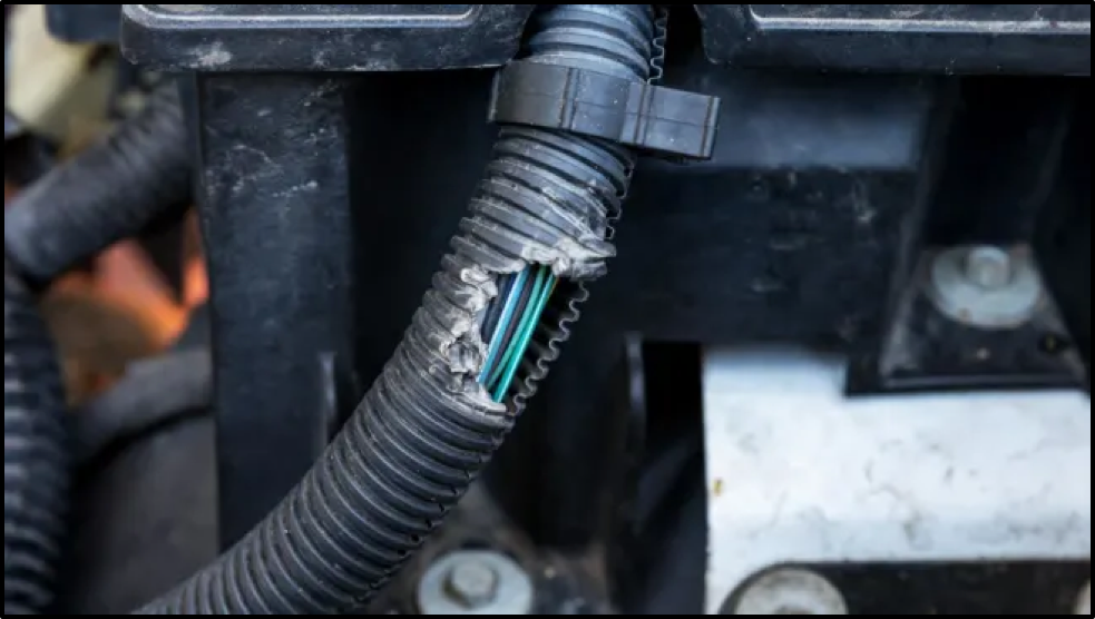
Figure 1: Vehicle Wiring Casing Chewed by Rats (“How to Protect Your Car From Rodents”, 2021)
Rat populations are on the rise; with the increase in global temperatures, shorter and warmer winters support rat breeding (Atkin, 2017). Meanwhile, the auto industry’s transition from petroleum-based wire insulation to more environmentally friendly soy-based products has reportedly fueled increased rat activity in vehicles (Brulliard, 2020; “Spotlight: Rodents”, 2013). Costly rat-related vehicle damage like chewed wire casings (Figure 1) or rubber hoses is not a dwindling problem, but an escalating dilemma. Conventional solutions include the spraying of various rat-deterrent scents like peppermint oil, cayenne pepper and mothballs (“How to Protect Your Car From Rodents”, 2021). However, this is inconvenient to car owners who must reapply scents regularly for maintained efficacy. Other solutions include encompassing rubber hoses with metal mesh or wrapping Honda’s $43 rodent-deterrent tape, treated with capsaicin for deterrence, around areas at high risk for rat damage (“How to Protect Your Car From Rodents”, 2021). These solutions, however, are difficult to apply. Meanwhile, an electronic-based rat deterring product has been designed for use in the engine bay (Figure 2).
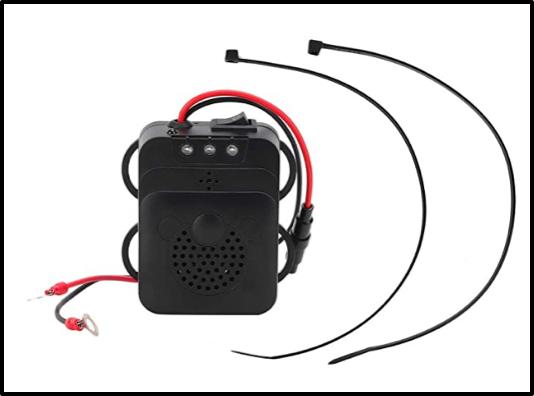
Figure 2: Current Product for Vehicle Engine Bay Application (“Vehicle‑Mounted Rat Repellent”, n.d.)
Utilizing both ultrasonic sound and flashing light to deter rats, this product, costing $24.59, appears to be a viable solution (“Vehicle‑Mounted Rat Repellent”, n.d.). However, Lavoie and Glahn (1977) found that rat feeding activity began to increase after only one week of exposure to ultrasonic sound. It follows, then, that sustained ultrasonic sound does not have long-term effectiveness in minimizing rat damage to vehicles. Moreover, the flashing lights and buzzer offer unnecessary drain on the car battery. The aim of this project is to mitigate these design flaws by the utilization of a motion sensor. While saving unnecessary battery drain, a motion sensor offers the added benefit of having ultrasonic sound activated only when necessary. This offers a potential solution to the acclimatization of rats to ultrasonic sound.
Materials and Methods
Circuits were created using TinkerCAD’s circuit builder and were designed to be built on a breadboard for both simplicity and repeatability. Circuits were then prototyped.
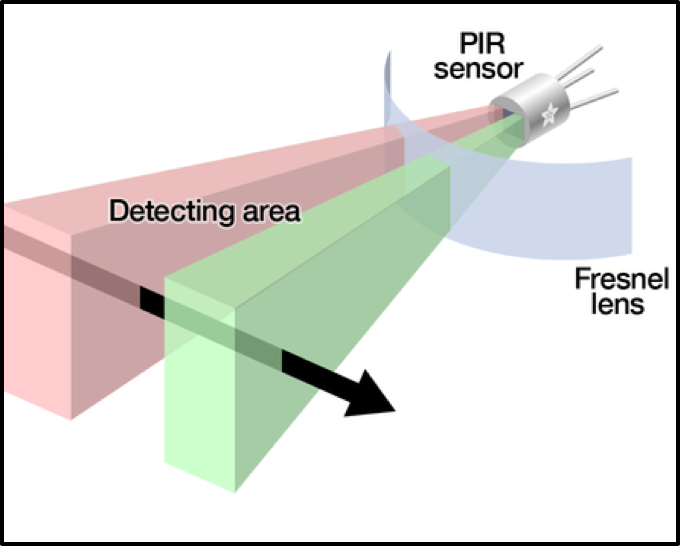
Figure 3: Passive Infrared (PIR) Motion Sensor (Ada, n.d.)
Both circuit designs utilize a PIR motion sensor to detect movement and to initiate the circuit. PIR motion sensors detect infrared radiation through two slots. When a human or animal passes in front of the motion sensor, one of the two slots detects movement first, creating a detectable differential as seen in Figure 3 (Ada, n.d.).
Design 1
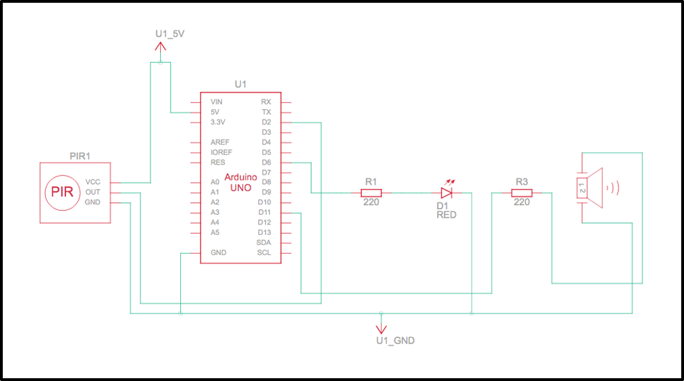
Figure 4a: Design 1 Circuit Diagram in TinkerCAD
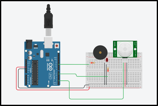
Figure 4b: Design 1 Circuit Model in TinkerCAD
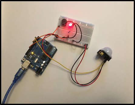
Figure 4c: Design 1 Circuit Prototype
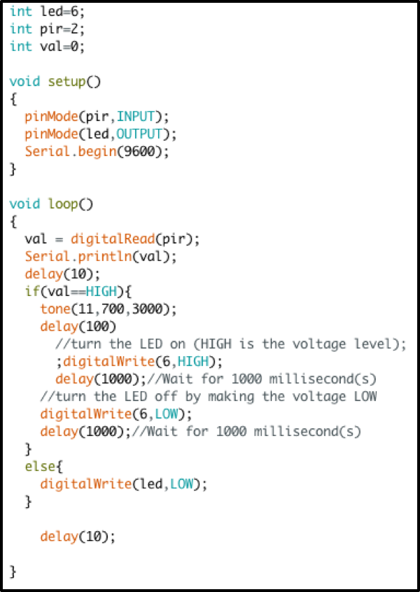
Figure 5: Design 1 Arduino Uno Code
Design 1 was created for use with an Arduino Uno, an LED light, a passive buzzer, an HC-SR501 PIR motion sensor and two 220 Ω resistors. Pictured in Figures 4a, 4b and 4c are the circuit diagram, circuit model and circuit prototype, respectively. The code attached in Figure 5 controls the circuit’s functions. Because the HC-SR501 PIR motion sensor distributes binary code (0 when no motion is detected; 1 when motion is detected), the flashing light and passive buzzer are programmed to begin when the input value of the PIR sensor is high. The HC-SR501 PIR motion sensor has adjustable sensitivity and time delay. For this circuit, the highest possible sensitivity and time delay were utilized. The time delay dictated that the circuit would run for roughly three and a half minutes after the detection of motion. Furthermore, the flashing light has a delay of 1000 milliseconds. This means that, as the light flashes, it powers on for 1000 milliseconds before powering off for 1000 milliseconds to create a pulsating effect. Meanwhile, the passive buzzer utilized requires a signal source to dictate frequency. Thus, a tone function was used in the code to control buzzer frequency.
Design 2
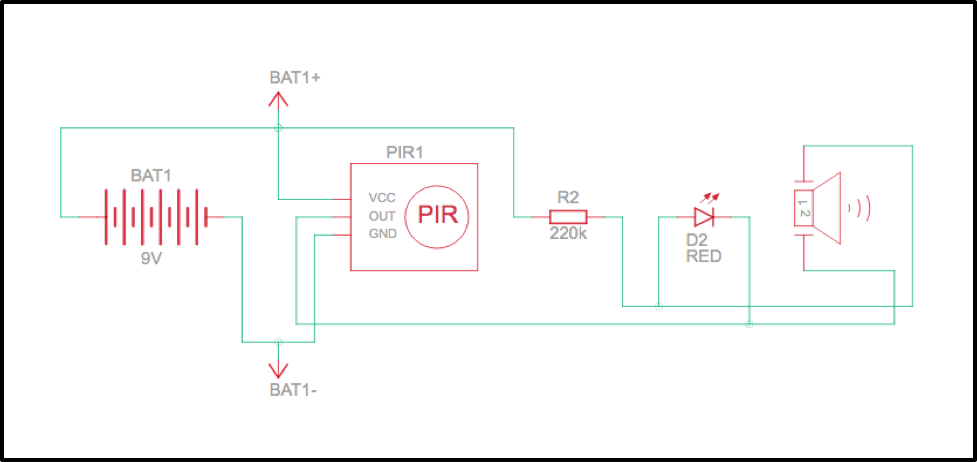
Figure 6a: Design 2 Circuit Diagram in TinkerCAD
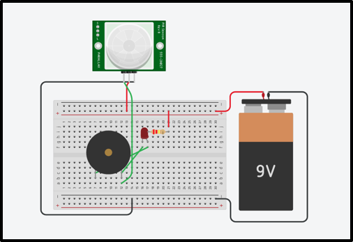
Figure 6b: Design 2 Circuit Model in TinkerCAD
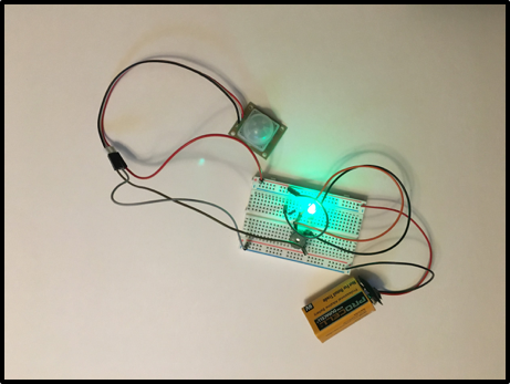
Figure 6c: Design 2 Circuit Prototype
Design 2 was created for use without any computer processing. This design utilized a 9V battery, a 220 Ω resistor, an LED, an active buzzer and an HP-208N PIR motion sensor. Pictured in Figures 6a, 6b and 6c are the circuit diagram, circuit model and circuit prototype, respectively. In the circuit model, an HC-SR501 PIR motion sensor was used in place of an HP-208N PIR motion sensor due to the limited supply of TinkerCAD circuit components. The model, utilizing an HC-SR502 PIR motion sensor, was designed for use with an HP-208N PIR motion sensor. The HP-208N PIR motion sensor has an open collector output pin. When no motion is detected, the output pin generates 9V. However, when motion is detected, the pin voltage output decreases to 0V. To offset the 9V from the output pin, an approximately equivalent voltage travels through the circuit from the opposite direction, resulting in a negligible voltage differential. When motion is detected and the output pin goes to 0V, however, there is a voltage differential traveling through the circuit which powers the LED and the active buzzer. An active buzzer was used for Design 2 because it does not require a signal source. Instead, active buzzers are simply ‘on’ if current travels through or ‘off’ if no current travels through. This is essential given the circuit’s lack of computing capabilities.
Results
Design 1 and 2 were both modeled using TinkerCAD and prototyped using a breadboard and circuit components. No real-world tests were conducted. Rather, the prototyped designs are proof-of-concepts for future product iterations.
Design 1
Design 1 functioned as intended to provide a proof-of-concept for a computational-driven rat deterrent. The use of the Arduino Uno in this circuit allowed for a flashing LED. Meanwhile, the use of the HC-SR501 PIR motion sensor permitted a lengthy three and a half minute circuit runtime after motion was detected. The Design 1 prototype cost roughly $40 CAD to build.
Design 2
Design 2 functioned as intended to provide a proof-of-concept for a motion sensor activated rat deterrent without computational capabilities. While Design 1 was controlled by an Arduino Uno, Design 2 was entirely controlled by the open collector output pin on the HP-208N PIR motion sensor. The Design 2 prototype cost roughly $20 CAD to build.
Discussion
While Design 1 and 2 both functioned as intended, each possesses inherent advantages and disadvantages. Design 1 is more effective in its rat-deterring potential due to the implementation of a flashing light. Flashing lights theoretically provide better rat-deterrence than bright light alone (“Using a Rodent Strobe Light as a Deterrent”, n.d.). The computational functionality of the circuit allows for this feature that circuit Design 2 could not implement. Moreover, the HC-SR502 PIR motion sensor employed in circuit Design 1 allowed for a time delay. This would be extremely beneficial in rat-deterrent applications; the light and buzzer would not turn off immediately after a rat is out of motion sensor range, but would continue functioning for a three and a half minute time period to discourage rats from lingering in vehicle engine bays. As evidenced, circuit Design 1 is more advantageous in deterring rats than circuit Design 2. However, Design 1 costs twice as much to implement as Design 2 because of the required computational capabilities.
While the proof-of-concepts could not be successfully prototyped for real-world testing due to a limited timeline and budget, the use of motion sensors in engine bay rat deterrents holds potential by mitigating issues present within current solutions. Scent-based deterrents are impractical because they must be reapplied, wire coverings like metal mesh or rat deterrent tape are unsuitable because they are difficult to install, and current electronic solutions are unsatisfactory because of unnecessary car battery drain and sustained ultrasonic sound. A motion sensor-based electronic solution could mitigate these issues. Requiring only a one-time installation, conserving vehicle battery life and transmitting ultrasonic sound only when necessary to ensure that rats cannot acclimatize, a motion sensor has potential in providing an effective rat deterrent method in vehicle engine bay applications.
To transition the article’s design ideas from proof-of-concepts to testable prototypes, a much brighter LED would need to be employed alongside an ultrasonic buzzer that emits sound frequencies above 20 kHz (“What is ultrasonic wave?”, n.d.). To make the designs practical in an engine bay, multiple motion sensors would need to be employed to decrease the likelihood that rats avoid detection. Since motion sensor waves cannot travel through hard objects, an engine bay is a difficult application of the technology (Tross, 2021). Although multiple motion sensors would increase product cost, it would also increase product efficacy. Field tests would be needed to decide upon the required number and location of motion sensors. Dependent on the number of motion sensors employed, the design ideas outlined in this article could become overly costly when compared against current products. Additionally, heat-proofing of circuitry would be necessary for a final rat deterrent product given that the temperature of engine bays can reach between 125℃ and 200℃ (“Taking the heat: plastics under the hood”,2016).
Evidently, much work needs to be done to implement this paper’s proof-of-concepts into fully-functioning products. However, the implementation of motion sensors as engine bay rat deterrents holds potential for multiple stakeholders. Consumers could avoid inconvenience, out-of-pocket repair bills and insurance deductibles while insurance companies could mitigate large repair bill payments (Boynton, 2020; Kearney, 2017). Since rat-related vehicle damage is increasing at alarming rates, an effective and convenient solution is needed.
References
Ada, L. (n.d.). How PIRs Work. adafruit. Retrieved February 3, 2022, from https://learn.adafruit.com/pir-passive-infrared-proximity-motion-sensor/how-pirs-work
Atkin, E. (2017, August). America Is on the Verge of Ratpocalypse. The New Republic. https://newrepublic.com/article/144392/america-verge-ratpocalypse
Boynton, S. (2020, January 3). Hungry rats led a man to file multiple ICBC claims. Then the insurer withheld the cheddar. Global News. Retrieved October 9, 2021, from https://globalnews.ca/news/6364600/icbc-rats-claims/
Brulliard, K. (2020, February). Rats will devour your car. The Washington Post. https://www.washingtonpost.com/science/2020/02/13/rats-will-devour-your-car/
How to Protect Your Car From Rodents. (2021, April). Consumer Reports. https://www.consumerreports.org/car-maintenance/how-to-protect-your-car-from-rodents-a5816950285/
Kearney, C. (2017, September 29). Rat damaged car engine leads to $15K repair bill. CBC News. https://www.cbc.ca/news/canada/british-columbia/rats-damage-cars-1.4312381
Lavoie, K., & Glahn, J.F. (1977). Ultrasound as a deterrent to Rattus Norvegicus. Journal of Stored Products Research, 13(1), 23-28.
Spotlight: Rodents. (2013). Pest Management Professional, 81(11), S13.
Taking the heat: plastics under the hood. (2016, March). Automotive World. Retrieved February 4, 2022, from https://www.automotiveworld.com/articles/taking-heat-plastics-hood/
Tross, K. (2021, October 12). The Beginner’s Guide to Motion Sensors. Safewise. Retrieved February 4, 2022, from https://askinglot.com/open-detail/541504
Using a Rodent Strobe Light as a Deterrent. (n.d.). HumanPestControlTips.Com. Retrieved February 4, 2022, from https://www.humanepestcontroltips.com/rodent-strobe.shtml
Vehicle‑Mounted Rat Repellent, Pest Repeller, Home Mice Deterrent Appliance, Rat Repellent, Car Vehicle for Pest Mouse. (n.d.). Amazon. Retrieved February 3, 2022, from https://www.amazon.ca/Vehicle%E2%80%91Mounted-Repellent-Repeller-Deterrent-Appl%20iance/dp/B08P5W2MXG/ref=sr_1_45?dchild=1&keywords=rat%2Bnoise&qid=%201633835724&sr=8-45
What is ultrasonic wave? (n.d.). Sonotec. Retrieved February 4, 2022, from https://www.sonotec.com/en/column/ultrasonic.html#:~:text=Ultrasonic%20wave%20is%20defined%20as,is%20also%20called%20ultrasonic%20wave