Michael Hewko, Year 2 Engineering
Abstract
Legged locomotion applied to robots or vehicles is a topic of widespread interest, study and application. A hexapod (six-legged) robot was created using the Arduino platform to carry weight and cross complex terrain. The robot failed to walk due to desynchronization between servo motors and commands. Suggested fixes to this problem for future projects include adding sensors to the legs to detect positioning and using a mathematical model coded into the Arduino unit to correct leg placement.
Introduction
Locomotion of vehicles using mechanical legs is a topic of widespread interest, design and application (a more detailed overview of the history and evolution of legged robotics can be found in”An Overview of Legged Robots” (Machado and Silva, 2006). For instance, a paper from the DIMEAS-Department of Mechanical and Aerospace Engineering, Politecnico di Torino, Turin, Italy used a 3D simulation of a bipedal (two legged) walker and found that additional compliance in the knees was most conducive to overall performance (Maiorino et. al, 2020). A variety of famous examples such as Honda’s Asimo (Sakagami et. al, 2002) or Boston Dynamics’ BigDog (Playter et. al, 2006) have captured public attention or been used to solve real-world problems. Legged vehicles have the advantage of crossing rougher and/or more complicated terrain than wheeled vehicles. This has applications in military settings allowing troops to carry supplies off-road, or in senior care as bipedal androids become increasingly lifelike. In this experimental prototype, a hexapod (six-legged) robot was created for search-and-rescue operations, with the intent of creating a small machine that can traverse complex, narrow spaces such as rubble after an earthquake to search for, and deliver items to, survivors.
As the project progressed, the intent began to shift. This is because the size limitations of the Arduino platform (specifically, the servo motors used) prevented an insect-sized robot from being created. Locomotion was also found to be more difficult than anticipated. Therefore, the primary focus of the project was narrowed down to enabling the ability to walk. After this however, a variety of technical and organizational problems arose that prevented final and timely completion of the project. Attempts to fix these errors resulted in a long and detailed iterative design process discussed in greater detail in the results and conclusion sections of the report along with possible solutions.
Materials and Methods
For this project, the ‘ELEGOO’ Arduino starter kit with Arduino UNO R3 board and expansion board were used (Part number EL-KIT-003) (IMPORTANT: the board which came with the kit ordered appeared to be defective and was replaced with a board of the same model with an unknown brand from Science World). 15 additional 9 gram 4.8V PWM “SG90” (Part number MS18-B) servo motors were ordered from the “Miuzei” brand. A Chapmans’ ice cream tub lid (from the 1L container) was used as a baseplate on which six holes were cut, 3 on each side. Each hole was sized according to the base and width of each motor so that they could be mounted to the platform with screws. A picture of the main chassis after mounting of the first 6 motors can be found in figure 1.
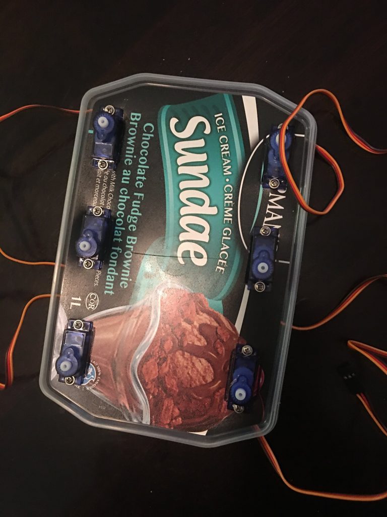
Figure 1: Main platform with holes cut and six servo motors installed
Part of the tub was cut to form a bridge glued to the top that carries the Arduino mainboard and extension board. Underneath the bridge, holes were drilled and a band was run though to fasten a 9-Volt battery to the chassis. Plastic brackets included with the servos were installed, then small plastic sheets were attached to the brackets. Six more servo motors were glued to the sheets sideways.
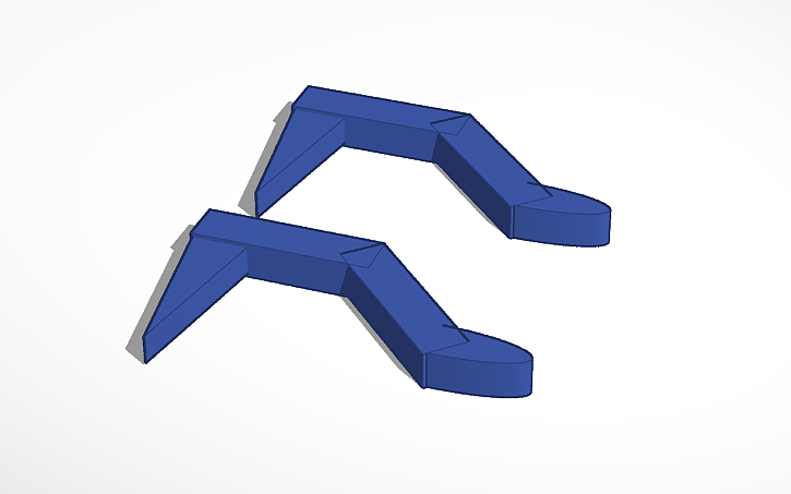
Figure 2: A pair of the robot’s legs as shown in the TinkerCAD software suite.
A total of six legs, a pair of which are pictured in the TinkerCAD software program, were printed using resin-based 3D printers at Science World (in figure 2 above). The legs were glued to another set of plastic brackets attached to the sideways ‘top’ servos. It was noted at this point that the ice cream tub lid would warp when the robot was standing, so three pieces of wooden dowling were cut and glued to the lid. Two ran across the robot’s width on the top half and one ran through its length. Diagrams of the complete chassis with legs attached can be found in figures 3-5. The motors were wired to 5V power, ground, and DATA ports as per Arduino instructions and guidelines. In the Arduino IDE, code was written in the C programming language to create an ordered series of leg movements to move the robot forward.
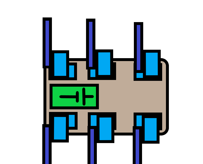
Figure 3: Early robot diagram, top-down view, the light blue boxes represent the servo motors, the dark blue represents legs, and the green with a battery cell diagram represent the bridge where the Arduino board and 9V battery are attached.
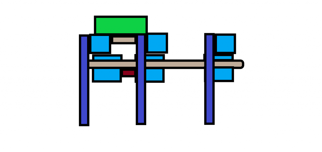
Figure 4: Same colour coding as figure three, but the robot has been turned to show its left and right side profile (the robot is symmetrical). The red indicates the 9V battery mounted to the bottom of the chassis.
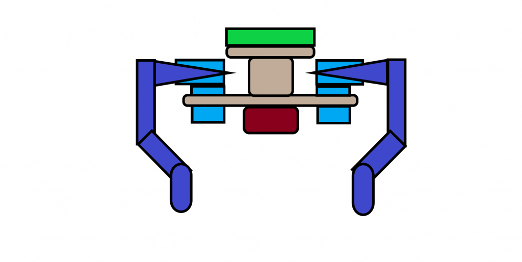
Figure 5: Same colour coding as figures 3 and 4, but from a frontal view of the robot.
Results
The robot did not function properly and at a sufficient capacity to undergo trials within the allotted time. A number of errors occurred during the process after construction, described below:
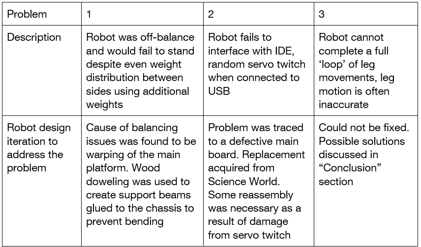
Table 1: Lists problems encountered and solutions implemented to provide an overview of the iterative design process.
Discussion
The robot was incomplete due a variety of unforeseen time constraints, challenges, and two design flaws that only became apparent when finishing construction/beginning testing. A large amount of production time was lost in 3D printing as it was underestimated the amount of time that the process would take. 3D printing involves extensive trial-and-error due to print failures and various design flaws and conflicts as well as large time frames to do the actual printing (each leg took around an hour to print after all problems with the printing had been solved). This took place over several weeks and constricted the time available for testing. Given this, it is recommended that 3D printing be used extensively for prototyping purposes and earlier in the design process.
The first additional challenge was a simple construction error that was easily fixed by adding wooden beams to improve the structural rigidity of the chassis. It was also noted that recycled plastics may not be the best construction materials even for small robots because of their poor rigidity. The second problem seemed to be a problem with the ability of the stock board to interface with the Arduino IDE. It did not appear to be a USB error on the computer used to write code since other USB devices had full functionality on the same USB port. The driver software included with the Arduino IDE did not appear to be functional when connecting the board to the computer. The IDE gave no feedback when the board was connected, and options to download code to the robot were absent. The problem was eventually resolved when the board was replaced with one of an identical model from Science World.
The critical failure encountered was when, after successfully coding and allowing the robot to ‘stand up’, the robot was incapable of moving on its own. When turning on the board, the servos would still ‘twitch’ but only once (so it was assumed that it was not a problem). However, the servos lacked encoders and did not move in exact adherence to the commands (for example, a command to move 60 degrees left would move by approximately 55-65 degrees). As they continued to move this became an increasing problem, especially when paired with the resistance of the robots’ weight as it stood. This would quickly cause the robot to exhibit desynchronous movement to the extent that it would fall. Not only that, but the discordant movements, when allowed to continue for too long, would pull the legs into the chassis and break them off, requiring lengthy replacement before continued testing.
The aforementioned error can still possibly be solved; however, it would require an overhaul of the robots’ design. A mathematical model would have to be devised whereby the locations of the legs are tracked and their deviation is converted into a variable, converted into degrees and used to send minor commands to individual legs to correct their positions as the robot moves. This would require the use of servos that have encoders, or sensors on the legs that detect the distance between other sensors. This would also require a board with greater storage and computational ability in order to store and utilise such a model.
In short, the extent of the project’s complexity and supply demand was drastically underestimated. It was believed that creating simple legged locomotion was simply a matter of building a standing robot and looping a series of commands to create a walking pattern of movement. In reality, the subject is far more complex (and the attempts to produce it even more so) than could have been completed given the available supplies and time.
References
Machado, José A. Tenreiro, and Manuel F. Silva. “(PDF) An Overview of Legged Robots.” ResearchGate, MME 2006 Conference, Apr. 2006, www.researchgate.net/publication/258972509_An_Overview_of_Legged_Robots.
Maiorino, Andrea, and Giovanni Gerardo Muscolo. “Biped Robots With Compliant Joints for Walking and Running Performance Growing.” Frontiers, DIMEAS-Department of Mechanical and Aerospace Engineering, Politecnico Di Torino, Turin, Italy, 26 Feb. 2020, www.frontiersin.org/articles/10.3389/fmech.2020.00011/full.
Playter, R., et al. “BigDog.” Researchgate, SPIE 6230, Unmanned Systems Technology Conference, May 2006, www.researchgate.net/publication/253126585_BigDog.
Sakagami, Yoshiaki. “The Intelligent ASIMO: System Overview and Integration.” Researchgate, IEEE/RSJ International Conference on Intelligent Robots and Systems, Feb. 2002, www.researchgate.net/publication/3972237_The_intelligent_ASIMO_System_overview_and_integration