Kai Cho, Year 2 Engineering.
Abstract
Despite being a hidden and smaller mechanism, catch basins (street/storm
drains) play a crucial role in preventing urban floods. Catch basins are found in convenient positions to drain streams of water from civilian streets. While there have been small efforts to prevent clogging such as pedestrian monitoring and filter barriers, catch basins are still vulnerable. StorEMER, an engineered device using an Off-Delay Timer circuit to fit a proof of concept end product was created to solve this problem. With relatively inexpensive parts, minimal energy usage and a compact design, catch basins can be cleared without monitoring. By utilising the Off-Delay Timer’s function of turning on for a specified time to control a DC Motor, the basin’s clogged grate would be swept with a blade attachment. With additional research and resources, the product may also be able to be self-sustaining, being a valuable asset for flood prevention in urban areas.
Introduction
Catch basins, or storm drains, are common in rainy cities such as Vancouver. There are over 45,000 catch basins found across Metro Vancouver (CBC News Writers, 2018); however, with climate change impacting the predictability of flash floods, urban areas can still be affected (Denchack, 2019). Cities such as Vancouver acknowledge catch basins as a valuable prevention system (City of Vancouver), but they can be rendered useless if not maintained during a flash flood. Cities encourage citizens to
help clear clogged catch basins and send crews to maintain them (Coquitlam Community), but during flash floods these tasks can be difficult to execute (See Figure 1).

Figure 1: Example of common storm drain clog (CBC News Writers 2018)
Upon doing research, the only catch basin blockage prevention found was a filter sock insert (See Figure 2),
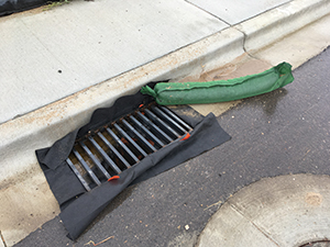
Figure 2: Filter sock insert in urban street drain (Hesselgrave 2019)
an invention implemented by cities (Coquitlam Community). While these are great for average rainy days with less debris being caught in side-road streams, they can be overrun and clogged during flash floods (City of Portland). With StorEMER, the objective was to test if it was possible to mount circuitry upon a catch basin, easily clear any clogging, use minimal energy and ensure implementation would be cheap and efficient. With the circuit mounted directly over a catch basin, a blade attached to a DC motor could easily get an angle on the catch basin, sweeping debris off the grate.
However, much of the time allotted for the project was spent finding a design, modelling it and building it, which was repeated for many attempts. It is important to note that although much testing and a final prototype was unable to be completed, the core of the project discussed in this journal can be used as proof of concept for the desired end product.
Materials and Methods
All designs were tested on TinkerCAD (See Figure 3),
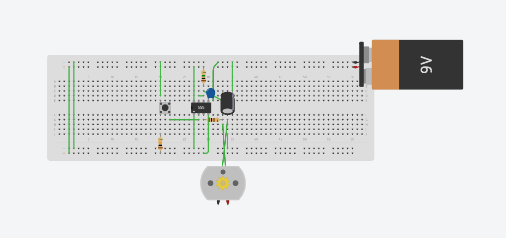
Figure 3: TinkerCAD circuit building working simulation of Off-Delay Timer Circuit (Cho 2021)
a computer aided design software that holds circuit building capability. It is important to note that all circuits were built on a basic small breadboard for ease of experimentation, and connected via wire connectors or the part’s included connector. Breadboards provide clean manageable designs, and are beneficial for replication. Multiple previous designs were created in TinkerCAD, but were unsuccessful and not included in this article as they were unnecessary for explanation. A multimeter was also used to test the working functions in the circuit. After a single failed attempt due to a
short-circuited 555 Timer IC, the second attempt for the Design 3 circuit was
successful.
Design 1:
The original design for the project consisted of 4 piezo elements (Lee’s Electronics 18584), 4 basic springs (3-¼” x 13/16”), a 12 V DC Motor (Lee’s Electronics 18702) and a 12 volt battery. Originally, the piezo elements were implemented to act as a self sustaining energy supply, charging the continuous motor. One end of the springs were intended to position against the incoming stream of debris, and the other ends attached to the piezo elements. The springs would trigger the piezos upon impact of the debris against its other end. A DC motor would be positioned above the catch
basin to clear the debris.
Design 2:
The concept was to have debris in the stream of the catch basin bump a thin strip of plexiglass or metal, which would be attached to a spring on the strip’s other end that triggers a single piezo element. The piezo element would signal to the battery to turn on, therefore powering the motor. With the thin strip at the point between the stream of debris and the catch basin, these parts would be positioned above the catch basin on a mounted construct (See Figure 4).
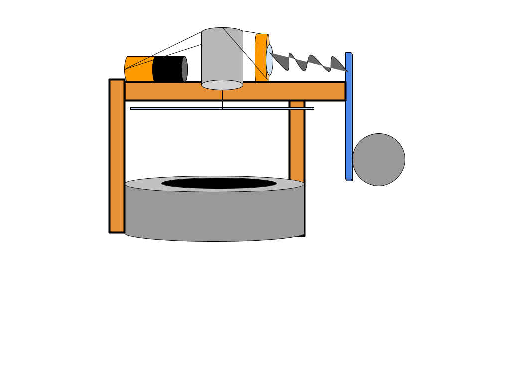
Figure 4: Conceptual design for end product (Cho 2021)
This design was essentially the same as Design 1, with the only difference being in the way the debris interacts with the piezo element.
Design 3:
The goal for this design was to have the designed circuit attached to the mount mentioned in Design 2. Acknowledging that there would need to be a system to turn the motor on and off, an Off-Delay Timer circuit was implemented. Time Delay circuits are common for the delay function required, and can be built in multiple different ways (Swagatam). Using the “Adjustable Auto On Off Delay Timer Circuit Using 555 IC” circuit diagram (Elonics) (See Figure 5),
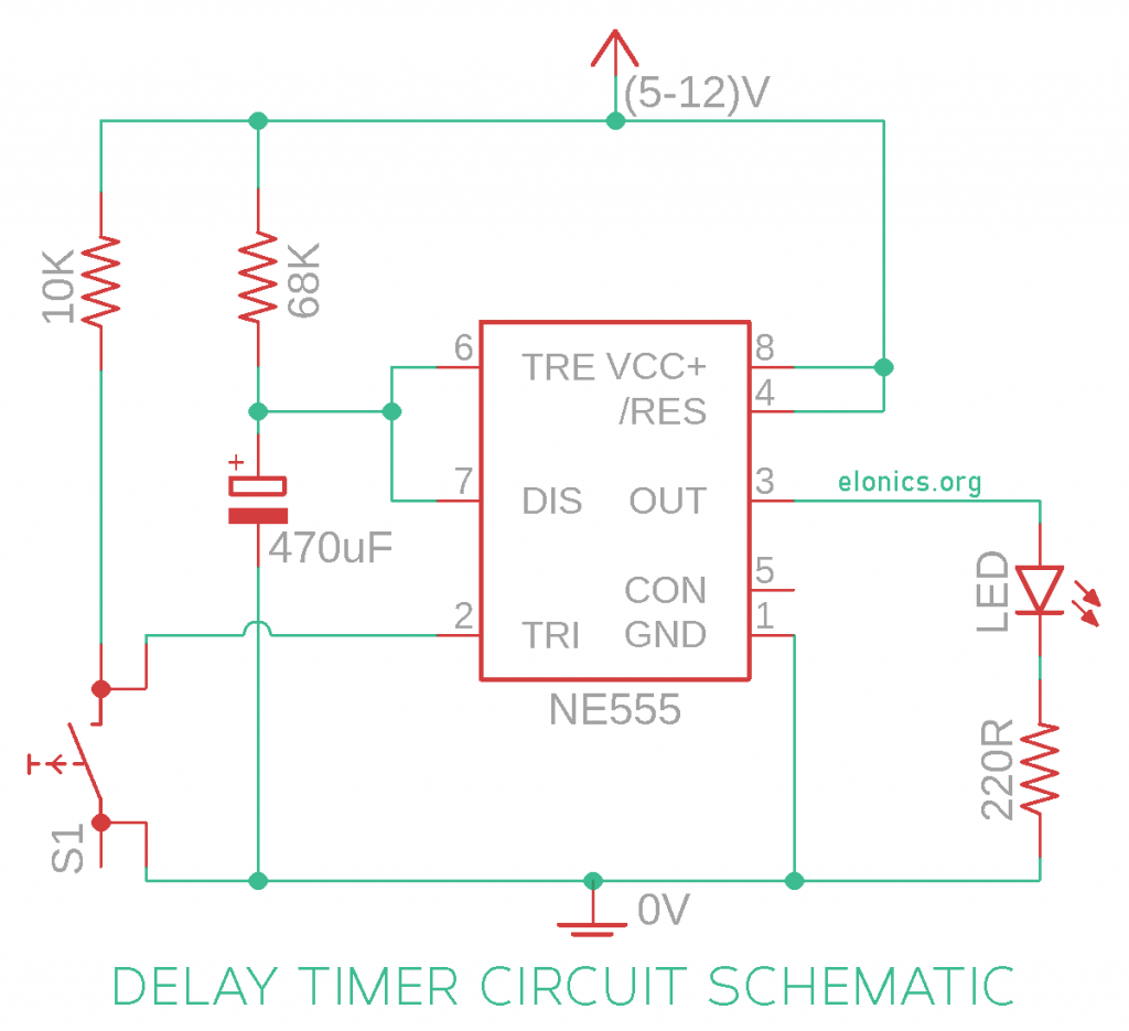
Figure 5: Circuit diagram for Off-Delay Timer Circuit (Elonics)
a successful model was completed. The circuit contained a 555 Timer Integrated Circuit (Lee’s Electronics), 10µf (microfarad) Polarized Capacitor (DigiKey), 0.105 µf Ceramic Capacitor (DigiKey), Momentary Push Switch (normally open)(DigiKey), 9 volt battery (Duracell), 12 wire connectors, one 120 kilo ohm resistor, one 10 kilo ohm resistor, one 220 ohm resistor, and a 3 volt motor (DigiKey). However, in this project an LED was substituted for the motor, as the motor originally intended for the design was unsuccessful in working. The circuit works by mainly utilizing the function of the 555
Timer IC. The 555 Timer IC contains 8 pins, Ground, Trigger, Output, Reset, Control, Threshold, Discharge and Supply Voltage, 1-8 respectively (See Figure 6).
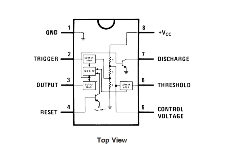
Figure 6: Pin overview and inside of 555 Timer IC (Hassaei)
When the Momentary Push Button closes the circuit, ground voltage is fed through the Button, and to the Trigger pin. This activates the Output pin, for which the LED is able to turn on through from the internally connected voltage from the positive rail. Concurrently, voltage from the positive rail is sent to the 10µf Polarized Capacitor, which acts as a storage for the charging voltage. When the Capacitor reaches ⅔ of the voltage supplied, the Output pin is disconnected from any voltage, turning the motor off. This is where the timing comes in. In this circuit, the purpose of the resistor connected to supply voltage is to control the time it takes for the capacitor to charge,
which is also dependent on the farad capacity of the capacitor itself. This circuit process is then repeated. In the case of the circuit built in this project, a 120 kilo ohm resistor was used. By using the equation (Elonics),
𝑡 = 1. 1 × 𝑅 × 𝐶
● 1.1 being the time constant it takes for the Capacitor to complete a charge cycle
to 66% (See Figure 7)
● R being resistor value in Ohms
● C being Capacitor value in farads

Figure 7: Capacitor charging chart (Reviseomatic)
the time delay can be calculated. Therefore, with this circuit using a 0.00001 farad capacitor and 120000 ohm resistor, the time delay is:
(1.1 x 120000 x 0.00001) = 1.32 seconds.
This was tested by placing a stopwatch next to the circuit and recording a slowed video of the circuit turning .
Results
Design 1:
After research, the battery would drain very quickly, as the piezo could not produce enough voltage to keep the motor running. A TinkerCAD simulation was unable to be crafted due to the missing piezo elements on the software.
Design 2:
Upon much configuration and research, this design was deemed impractical. The piezo alone could not tell the battery to turn on, and there would be no trigger to turn the motor off. Again, a TinkerCAD simulation was unable to be crafted. However, this design proved to be a useful starting base.
Design 3:
Design 3 was ultimately the only successful model to be built both as a TinkerCAD simulation and a prototype (See Figure 8).
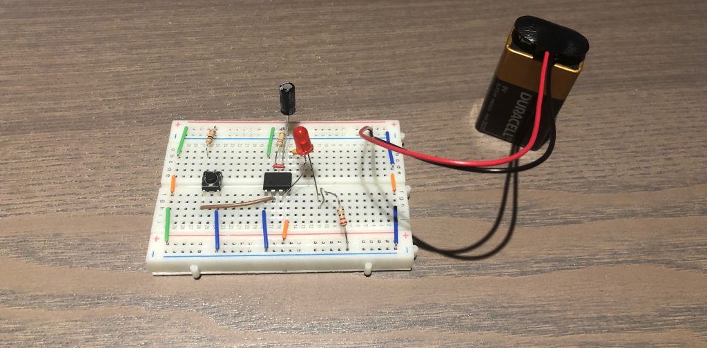
Figure 8: Off Delay Timer circuit (Cho 2021)
Using minimal energy, costing under 30$ CAD, and built with efficient implementation, the project was successful in representing the circuit control function of “StorEMER”. The circuit had a time delay of 1.38 seconds, which was tested multiple times. Mounting and testing were unable to be completed.
Discussion
The 0.06 second difference between the theoretical time delay (1.32 s) and the tested time delay (1.38 s) was most likely due to a leakage of the capacitor (Elonics). Nonetheless, this timing of delay was near perfect for the desired end product, as having the motor stay on when the debris reaches the catch basin is the goal. This timing could easily be tweaked if need be by changing the values of the resistor and capacitor, according to the previously mentioned equation and this chart (See Figure
9):
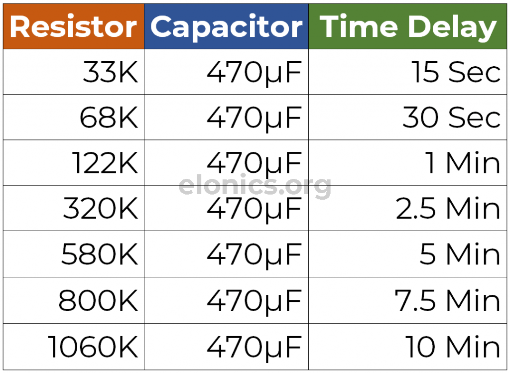
Figure 9: Resistor-Capacitor relationship chart for adjusting the time delay (Elonics)
Due to the experimental method of designing, TinkerCAD was necessary. This was useful for creating designs, but also limited what was available in terms of circuit pieces as use of piezo elements in TinkerCAD was not possible. To further this experiment, there would be a number of additions that would result in the desired end product. An NPN Transistor would have to be implemented for the original motor to work, or to allow the current and voltage to be sufficient for a larger DC Motor. Debris
on catch basins can be heavy, and a large motor would be more effective with clearing any debris. The debris would be swept away from the catch basin and a mesh catcher bag for the debris could be placed for easy removal. Although the momentary push button could act in the piezos place as a trigger for the circuit using the spring from Design 2, the addition of a knock-on piezo circuit to the off-delay may also function. Using this “Triboelectric Hybrid Generator” design (Jung, Woo-Suk, et al. 2015), piezo
elements could be added and serve both the function of generating enough voltage for the circuit to run, and creating a storage of voltage. Quite possibly the most important addition to the end product would be waterproofing. Using a form of encapsulation (most likely in the form of a wood box) around the circuit with the addition of epoxy or silicone to cover would provide sufficient waterproofing. With the circuit on the constructed mount, damage risk would also be decreased as the circuit would be
further from contact with water. The prototype circuit built was sufficient to act as the control of the project. With the application of the previous points, StorEMER may provide a satisfactory end prototype, but further testing is required.
References
CBC News Writers. “Over 1,700 Vancouverites have ‘adopted’ storm drains.” CBC News, 1 Nov. 2018,
www.cbc.ca/news/canada/british-columbia/over-1-700-vancouverites-have-adopted-storm-drains 1.4888627#:~:text=There%20are%20over%2045%2C000%20catch%20basins
%20across%20Vancouver. Accessed 3 Apr. 2021.
City of Portland. “Why do we still have drainage and flooding problems after building the big pipes?” The City of Portland Oregon, www.portlandoregon.gov/bes/article/574879.
Accessed 24 Apr. 2021.
City of Vancouver. “Adopt a catch basin.” City of Vancouver,
vancouver.ca/home-property-development/adopt-a-catch-basin.aspx. Accessed 4 Apr. 2021.
Coquitlam Community. “Flood Protection.” Coquitlam, www.coquitlam.ca/222/Flood-Protection.
Accessed 2 Apr. 2021.—.
“Storm Inlet Protection.” Coquitlam, www.coquitlam.ca/249/Storm-Inlet-Protection. Accessed 3 Apr. 2021.
Denchak, Melissa. “Flooding and Climate Change: Everything You Need to Know.” Natural Resources Defense Council, Inc., 10 Apr. 2019,
www.nrdc.org/stories/flooding-and-climate-change-everything-you-need-know. Accessed
6 Apr. 2021.
DigiKey Electronics.
www.digikey.ca/en/resources/conversion-calculators/conversion-calculator-resistor-colorcode. Accessed 4 Apr. 2021.
Elonics – Electronics Projects on Breadboard. “Adjustable Auto On Off Delay Timer Circuit Using 555 IC.” Elonics,
elonics.org/adjustable-auto-on-off-delay-timer-circuit-using-555/. Accessed 10 Apr. 2021.
Hassaei, Amanda G. “555 Timer.” instructables, www.instructables.com/555-Timer/. Accessed 2 Apr. 2021.
Hesselgrave, Barbara. “Keeping Sediment Under Control.” StormWater, 2 Jan. 2019. Accessed 7 Apr. 2021.
Jung, Woo-Suk, et al. “High Output Piezo/Triboelectric Hybrid Generator.” Sci Rep, vol. 5, no. 9309, 30 Jan. 2015. Nature, doi:10.1038/srep09309. Accessed 2 Apr. 2021.
Lowe, Doug. “Electronics Components: How the 555 Timer Chip Works.” dummies,
www.dummies.com/programming/electronics/components/electronics-components-how-the-555-timer-chip-works/. Accessed 3 Apr. 2021.
Reviseomatic. “RC Timing Circuits.” Reviseomatic,
reviseomatic.org/help/s-capacitors/Capacitors%20-%20RC%20Timing.php. Accessed 2 Apr. 2021.
Swagatam. “Simple Delay Timer Circuits Explained.” Homemade Circuit Projects,
www.homemade-circuits.com/simple-delay-timer-circuits-explained/. Accessed 3 Apr.2021