Flora Guo, Year 2 Engineering.
Abstract:
Inspired by the need for sustainable, compact power sources for wearable devices and novel LED light-up shoes, this project aims to design, build, and test a “proof-of-concept” piezoelectric insole. Four piezoelectric pads were attached to a foam insole and wired to bridge rectifiers in parallel. The output of the insole was tested with a multimeter as a potential function of pressure applied to the pads and the number of pads pressed. This project found that the generated voltage is dependent upon only the pressure applied when the pads are wired in parallel. The final insole was generated 1.5 of DC current, but further improvements must be made before the insole can be considered a viable power source.
Introduction:
As wearable devices boasting both clinical and fitness and activity tracking applications (Khalid et al. 2019) are increasingly integrated into healthcare, the need for a compact, independent power source has been heightened. These devices range from smart watches to adhesive patches used to monitor human vital signs such as heart rate, respiratory rate, blood saturation, blood pressure, and body temperature (Dias and Cunha, 2018). The convention of electrochemical cells to suit this demand has failed due to its finite energy storage capacity and its potential hazard to both human health and the environment (Zhao and You, 2014). To fill this demand, a novel solution is investigated: harvesting mechanical energy from human motion (Starner, 1996). The inspiration for this project originated from the LED light-up shoes often worn by children. I wondered how the shoes lit up once a step was taken, which led me to research piezoelectric components. I was intrigued as to whether this could be a reliable source sustainable energy and this interest culminated in my project.
The process by which energy on the scale of nW to μW is collected and transformed into useful electrical energy is known as energy harvesting (Yusuf et al, 2013). Energy can be harvested from ambient sources such as mechanical vibrations, thermal gradients, solar energy, and rotational kinetic energy (Davidson and Mo, 2014). Yet human motion, more specifically the stepping the motion, is both plentiful and easy to harness via piezoelectric elements. Thus, this investigation seeks to design and build a “proof-of-concept” piezoelectric insole and explore its viability as a sustainable power source for wearable devices.
Piezoelectricity is the ability of a material to produce an electric voltage when placed under stress in the form of compression or expansion (Howells 2009). Piezoelectric materials are transducers, which means that they convert physical signals (mechanical stress) into proportional electric signals in the form of a voltage (Electrical4u, 2019). The piezoelectric element is a crystal containing randomly oriented locally polarized magnetic regions, which align when subject to mechanical stress (Chapman et al. 2017). As a result, one side of crystal becomes positively charged while the other becomes negatively charged, creating a potential difference (Piezotechnology: Fundamentals of Piezoelectricity) (Fig. 1). This potential difference then allows for electrons to flow through a load, enabling work to be done.
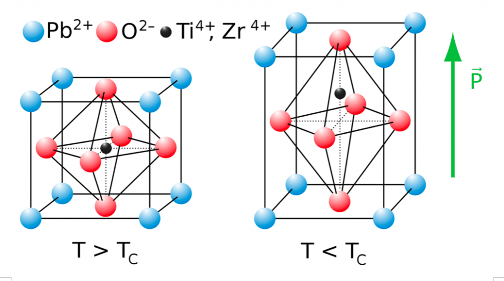
Figure 1: PZT piezoelectric crystal before (left) and after (right) mechanical stress, which represents the dipole density or polarization of the crystal. From: Pinin 5 Aug. 2010
Similar work has been conducted with the aim of converting human motion into useful electrical energy. In 2014, J. Zhao and Z. You created a shoe-embedded piezoelectric energy harvester insole that provided 1 mW of power at a 1 Hz step frequency. Their energy harvester utilized a polyvinylidene difluoride (PVDF) piezoelectric crystal, which is more flexible but less cost effective than lead zirconate titanate (PZT). Yet another example of piezoelectric elements in action is in Filipino college student and inventor, Angelo of channel ASCAS’s 2017 prototype of a step-powered shoe generator. Angelo wires his piezoelectric elements to a portable battery pack, which he uses to charge small electronic devices. Lastly, in 2017, students at New Jersey’s School of Engineering and Technology used piezoelectric elements to power a light-up shoe. The students were able to power a 7.4 V LED strip (approximately 300 LEDs in parallel) using two 3.7 V rechargeable Lithium-ion batteries as an energy storage system. They discovered that the circuit depicted in fig. 2 yields the highest efficiency for energy generation, which will be the starting point for the circuitry of this project.
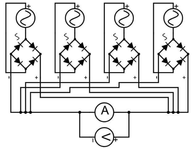
Figure 2: Energy harvester circuit diagram, From : Chapman N. et al. “Piezoelectric Energy Harvesting with 3-D Printed Light-up Shoe”
This project uses ten circular 27 mm diameter Lead Zirconate Titanate (PZT) piezoelectric elements mounted on a foam shoe insert (fig. 3). The voltage generated by the PZT piezoelectric pads are converted from alternating current (AC) to direct current (DC) and measured with a multimeter.
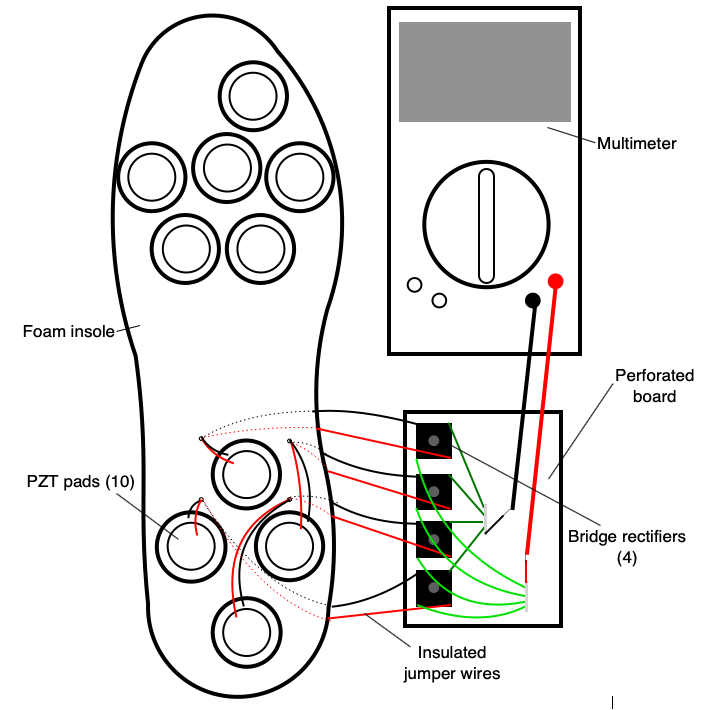
Figure 3: Sketch of completed piezoelectric insole (Flora Guo, 2020)
Materials and Method:
Ten PZT piezoelectric pads (Digikey) were placed onto the right-hand side insole (Better Feet) and the perimeter of each pad was traced with a ballpoint pen. A box cutter was used to make a circular cut along the drawn perimeter. 4 cm of the box cutter was exposed and used to saw away the fabric inside the circumference of the ballpoint outline, resulting in a cut-out 27 mm in diameter and 0.5-1.5 mm in depth that exposed the foam underneath (Fig.4). Each PZT pad was then secured into the cut-out using a square of double-sided foam tape of side length 1 cm. The leads of each PZT pad was threaded through ready-made perforations in the insole. Due to time constraints, only the bottom-most four PZT pads had insulated jumper wires soldered onto each of their leads (Fig. 5). Heat shrink tube segments 3 cm in length were threaded over each solder connection and shrunk with a heat gun.
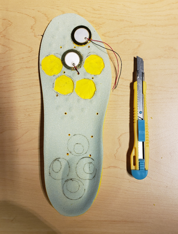
Figure 4: Removal of fabric cut-outs with box cutter on insole (Flora Guo, 2020)
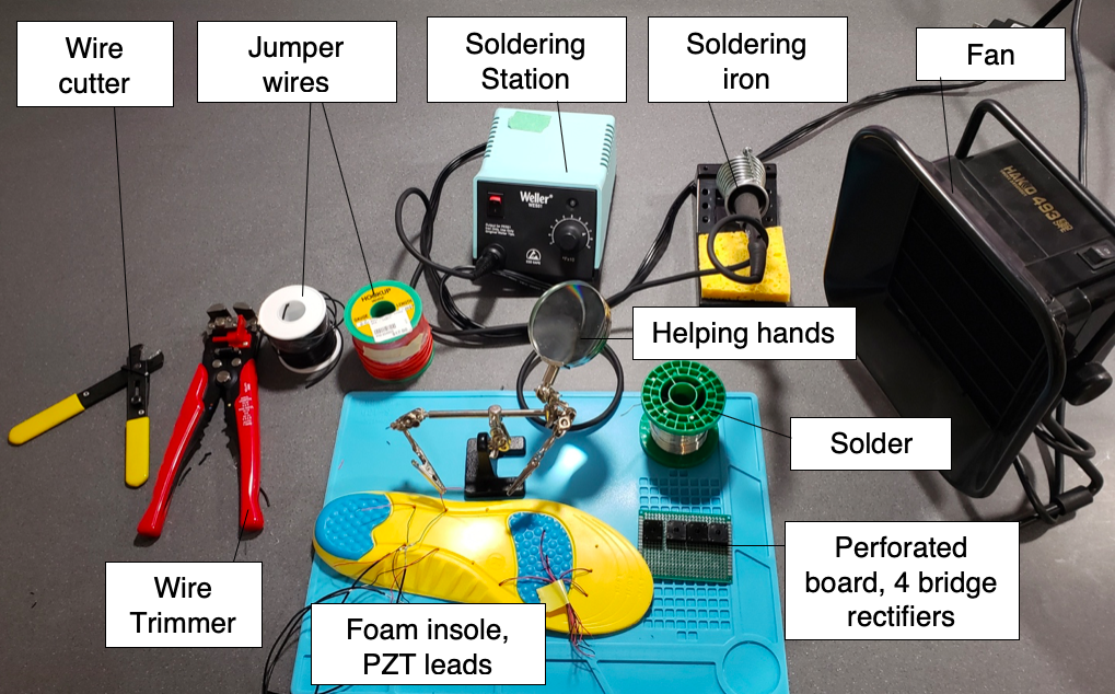
Figure 5: Workstation, soldering the PZT leads to insulted jumper wires (Flora Guo, 2020)
Wiring circuitry
Four bridge rectifiers (RPelectronics) were soldered onto a (23 × 18) hole perforated board (Elegoo) and the excess leads were trimmed with a wire cutter. The leads of the PZT pads were soldered onto the AC inputs of the bridge rectifiers. Insulated jumper wires were cut into 15 cm segments and the ends trimmed with a wire trimmer. The wires were soldered onto the DC outputs of each bridge rectifier. All of the positive leads were bridged together into a positive terminal with solder and the same was done for the negative leads. A small LED was soldered between the positive and negative terminals (note the polarity of the LED, wiring it incorrectly will cause it not to light). Approximately 0.7 cm of insulation was stripped off each end of two 5 cm segment of jumper wire. One end of each wire segment was then soldered to either the positive or negative terminals of the bridge rectifier outputs.
Testing the Electrical Output:
The leads of the multimeter were attached to the corresponding positive and negative terminals on the perforated board (Fig. 6). The multimeter was set to 2 V DC and one PZT pads was pressed with a “light” pressure once. The highest reading obtained was then recorded as the multimeter fluctuates rapidly after pressure is applied to the PZT (Fig. 7). This process was repeated for three trials, pressing a different PZT pad for each trial. Three trials were conducted each while pressing two PZT pads simultaneously and then three PZT pads simultaneously. Only three pads were tested, as the soldered connection on the leads of one of the four wired pads broke off. Afterwards, this entire process was repeated with both “moderate” and “high” pressures respectively. Note that “light” pressure is defined to be pressure that caused no visible deformation of the foam insole, “moderate” pressure causes the foam insole to compress by approximately 0.5 mm and “high” pressure causes the maximum deformation of approximately 1-2 mm.
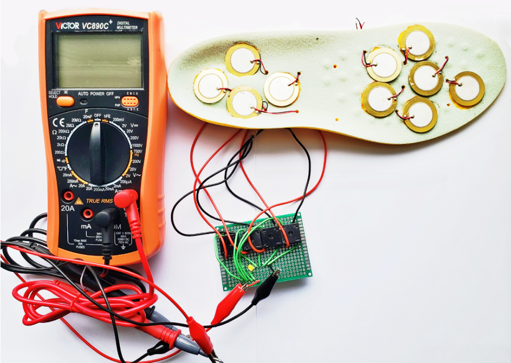
Figure 6: Piezoelectric insole connected to multimeter (Flora Guo, 2020)
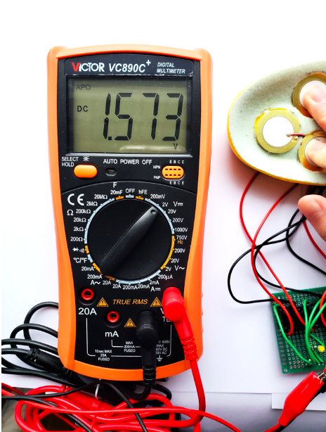
Figure 7: Collecting data from the insole with a multimeter (Flora Guo, 2020)
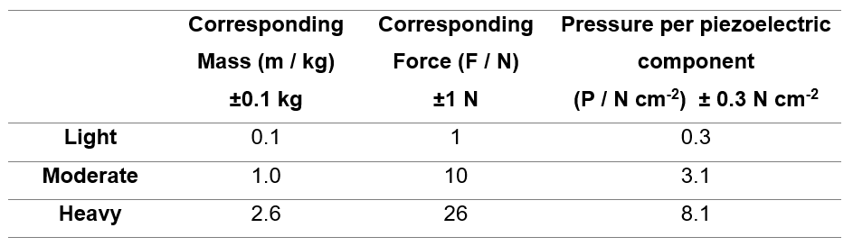
An approximation of the pressure applied per piezoelectric pad was found as follows:
Using an analog scale, the numerical equivalents of “light,” “moderate,” and “high” pressure were measured as masses (kilograms) and converted into force (Newtons) as shown in Table 1. To convert the measurements of mass into force, the mass is multiplied by a factor of g or 9.81 kg m-2, the acceleration due to gravity at the surface of the Earth. This approach is valid as the analog scale is essentially a Newton scale that converts the readings of force into the mass required to produce that force on the scale. An underlying assumption is that the scale is at rest, which is valid in this case. Considering that the ceramic area of the piezoelectric element is found as follows (radius of ceramic component of piezoelectric component, r is found in the component data sheet):
A = π r2 = π (1.00 cm ± 0.01cm)2 = (3.14 ± 0.06) cm2
The pressure applied to a single piezoelectric element was determined to be the force applied divided by the area of the ceramic component of the piezoelectric component (Table 1). For simplicity, is assumed that all of the possible area on the piezoelectric area is compressed.
Table 1: Pressure Applied per Piezoelectric pad
Results
To evaluate the effectiveness of the insole, a multimeter was used to measure both the voltage and the current produced (Table 2). An uncertainty of 0.1 V was determined on the output voltage, as the multimeter readings fluctuated rapidly after pressure was applied each time. I chose to vary both the pressure applied to the PZT pads and the number of pads pressed in order to explore potential correlations between both variables. The results indicated that greater pressures correlated to greater voltages produced. However, the number of PZT pads pressed simultaneously did not have a significant impact on the output voltage.
Table 2: Voltage Produced from Piezoelectric Insole
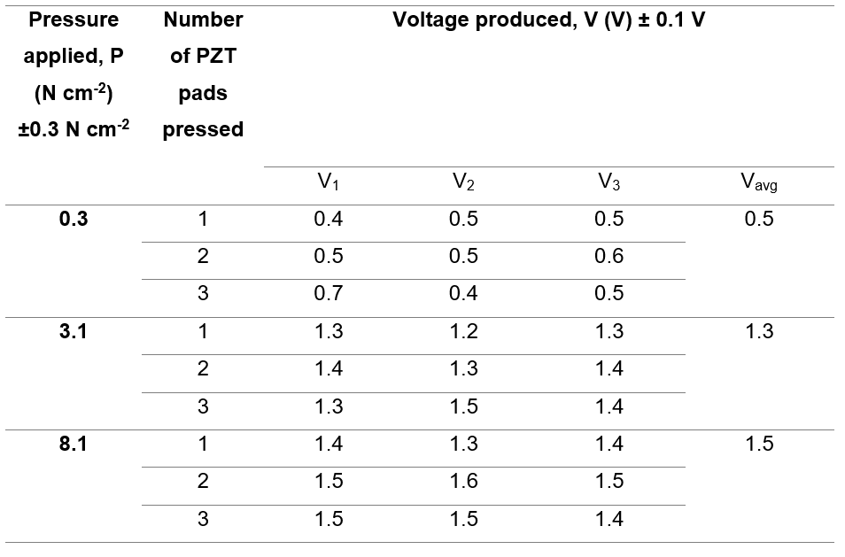
No current could be detected by the multimeter under any circumstances. After pressing all of the wired pads with a high pressure with the multimeter set to 200μA, the multimeter still gave no reading.
To visualize the relationship between the information in Table 2, the pressure applied per piezoelectric pad was graphed against the average output voltage (Fig. 8). The graph appears to show a positive relationship between the pressure applied and output voltage, however, the rate of increase of the output voltage decreases as the applied pressure increases. It should also be noted that no trend line was drawn on the graph due to a lack of data points.
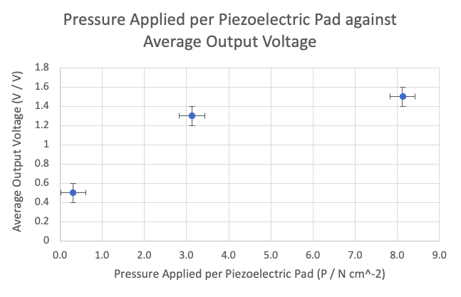
Figure 8: Graph of pressure per piezoelectric pad against average output voltage (Flora Guo, 2020)
Discussion
The insole generated a maximum of 1.5 V of voltage, but no discernible current was detected. As a result, no meaningful power was generated from the insole, rendering it incapable of powering any sort of device. The lack of current was likely due to the absence of a power management circuit. Although the AC signal from the PZT pads were rectified into DC by the bridge rectifier, the DC output was not stored in a useful manner before the piezoelectricity of the crystal reverts to zero when the mechanical strain is removed.
As this insole was designed to explore the viability of piezoelectric energy harvesting for the purpose of powering small wearable devices such as low-power smart watches and heart-rate sensors, the results obtained are understandable. This project demonstrated that inexpensive piezoelectric elements can be used to generate a noticeable voltage from a stepping motion. Nonetheless, the lack of an appropriate power management circuit resulted in the ineptitude of this project as a working prototype. This issue would be the main focal point if a second prototype were to be developed. In the context of healthcare and the applications of this product, improvements must be made to the design before the viability of a non-invasive human-powered generator can be confirmed. Nonetheless, these faults in design are only pointers into further areas for improvement.
In light of published findings, researchers such as Natalie Chapman and peers (2017) were able to bypass the issue of weak current and subsequent power with a power rectifying circuit. By utilising both a charge and discharge circuit that could be adjusted with a vertical switch, her team was able to store sufficient energy in an AA battery pack before discharging the power through a microcontroller and connected LEDs. The use of a microcontroller allowed for precise control of the power distribution, which is an aspect I would like to explore in the future.
With additional time, a power management circuit containing a resistor and capacitor in series (RC circuit) would be developed to build up and release the charge generated from the piezoelectric elements. Moreover, a double AA battery pack containing two rechargeable lithium ion batteries would be wired to the RC circuit in order to store the charge released by the RC circuit. To best control a potential power management circuit, a microcontroller such as an Arduino Pro Mini can be used to direct power to a load appropriately. Lastly, all ten of the piezoelectric elements would be included in parallel into the future circuit to maximise the potential current generated.
References:
ASCAS, Angelo. “Electricity Generating Footwear – Generate Electricity by Walking (Concept).” Instructables, 16 Oct. 2017, https://www.instructables.com/id/Electricity-Generating-Footwear/.
Chapman, Natalie, et al. Piezoelectric Energy Harvesting with 3-D Printed Light-up Shoe. New Jersey Governor’s School of Engineering and Technology, 21 July 2017, Retrieved from: https://pdfs.semanticscholar.org/7aa6/d4e5a2aa51631cb549795538bbde8164cb47.pdf.
CUI Inc., Piezoelectric Diaphragm Datasheet, 7 July 2006, Retrieved from https://www.cuidevices.com/product/resource/ceb-27d44.pdf
Davidson J., Mo C., “Recent Advances in Energy Harvesting Technologies for Structural Health Monitoring Applications” Smart Materials Research. Volume 2014; Article ID 410316, 14 pages. https://doi.org/10.1155/2014/410316
Dias D., Cunha J. P. S., “Wearable Health Technologies—Vital Sign Monitoring, Systems and Technologies” Sensors (Basel). 2018; 18(8): 2414. 10.3390/s18082414
Electrical4u, “Transducers: Types of Transducers and What They Are” Electrical 4 U. 25 July 2019. Retrieved from: https://www.electrical4u.com/transducer-types-of-transducer/
Khalid S., Raouf I., Khan A., Kim N., Kim H. S., “A Review of Human-Powered Energy Harvesting for Smart Electronics: Recent Progress and Challenges” International Journal of Precision Engineering and Manufacturing-Green Technology (2019) 6:821–85 https://doi.org/10.1007/s40684-019-00144-y
Pinin, “Tetragonal unit cell of lead titanate” (CC 0) File: Perovskite.svg, 5 Aug 2010. Retrieved from: https://en.wikipedia.org/wiki/Piezoelectricity#/media/File:Perovskite.svg
“Piezotechnology: Fundamentals of Piezoelectricity,” Piezo Mechanics Design Tutorial: Fundamentals of Piezotechnology, Piezo Tutorial. [Online]. Available: http://www.piezo.ws/piezoelectric_actuator_tutorial/Piezo_Design_part2 .php. [Accessed: 10-Mar-2020].
Starner T. “Human-powered wearable computing”. IBM Syst. J. 1996; 35:618–629. [Google Scholar]
Yusuf, S.T., Yatim, A.H.M., Samosir, A.S., & Abdulkadir, M., Mechanical Energy Harvesting Devices for Low Frequency Applications: Revisited. ARPN Journal of Engineering and Applied Sciences, 2013; 8 (7), 504-512. Retrieved from http:// www.arpnjournals.com/jeas/research_papers/rp_2013/ jeas_0713_911.pdf
Zhao J., and You S. “A Shoe-Embedded Piezoelectric Energy Harvester for Wearable Sensors.” Sensors (Basel, Switzerland), MDPI, 2014; doi: 10.3390/s140712497